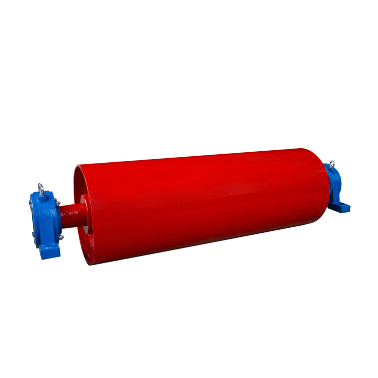
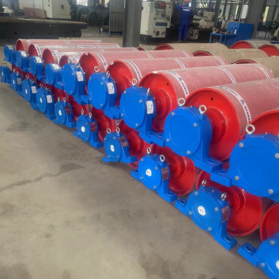
Tail Bend Pulley
Description

J&M's Tail Bend Pulley, also called the redirection roller, is an important part of the conveyor belt system. Its main function is to change the direction of J&M's Tail Bend Pulley. so that items can be transported in the opposite direction. In conveyor belt systems,J&M's Tail Bend Pulley are widely used in kind of places, playing a key role in ensuring the stability and accuracy of materials during transportation.
The working principle of J&M's Tail Bend Pulley is that after the motor is started, the J&M's Tail Bend Pulley starts to rotate. The material enters the redirecting drum with the movement of the drum and is brought to one side of the drum. In this process, the movement direction of the material is changed, thereby realizing a change in the conveying direction.
In addition,J&M's Tail Bend Pulley is also suitable for conveyor belt turns, such as Coal mining, Gold, Quarry, Rock or Stone mills, Power plant, Cement plant, Steel Mills, Coal washing plants, Salt works, Fertilizer plant, Facilities of Seaports or Airport, Overland Troughed Conveyor and so on. In these scenarios,J&Ms Tail Bend Pulley can effectively guide the material to turn, ensuring the smoothness and stability of the material during transportation.
It should be noted that the design and selection of J&M's Tail Bend Pulley need to be determined according to the specific conveyor belt system and usage scenarios. For example, factors such as conveyor belt width, speed, material type, etc. need to be considered to ensure that J&M's Tail Bend Pulley can meet actual needs. At the same time, regular maintenance and inspection are also required during use to ensure its normal operation and extend its service life.

After the drum is assembled, the radial runout tolerance of the outer circle shall comply with the requirements in the table below.
Unit:mm
|
PulleyD |
200~800 |
1000~1600 |
1800 |
|
|
Radial circular runout tolerance |
Non-Lagging Pulley Pulley |
0.6 |
1.0 |
1.5 |
|
Lagging Pulley |
1.1 |
1.5 |
2.0 |
|
|
D |
D |
A |
L |
L1 |
L2 |
I |
M |
H |
D |
B |
DS |
|
500 |
501 |
850 |
600 |
600 |
505 |
115 |
71 |
23 |
16 |
55 |
55 |
|
650 |
501 |
1000 |
750 |
750 |
582 |
125 |
91 |
23 |
16 |
72 |
72 |
|
531 |
732 |
175 |
91 |
23 |
17 |
71 |
71 |
||||
|
500 |
504 |
1300 |
950 |
800 |
771 |
175 |
130 |
23 |
91 |
71 |
91 |
|
631 |
871 |
115 |
130 |
23 |
91 |
91 |
91 |
||||
|
601 |
900 |
225 |
140 |
23 |
110 |
91 |
110 |
||||
|
1000 |
531 |
1500 |
1150 |
1300 |
871 |
255 |
170 |
23 |
120 |
110 |
110 |
|
601 |
200 |
225 |
140 |
23 |
110 |
110 |
110 |
||||
|
1000 |
1000 |
225 |
130 |
23 |
150 |
150 |
150 |
||||
|
1220 |
531 |
1750 |
1400 |
1350 |
1025 |
225 |
130 |
33 |
110 |
110 |
110 |
|
601 |
1058 |
275 |
220 |
33 |
150 |
120 |
110 |
||||
|
1000 |
1065 |
235 |
170 |
33 |
170 |
110 |
120 |
||||
|
1250 |
1150 |
235 |
180 |
33 |
140 |
150 |
110 |
||||
|
1420 |
801 |
2000 |
1600 |
1450 |
1150 |
275 |
130 |
E3 |
110 |
120 |
150 |
|
1000 |
1190 |
215 |
140 |
E3 |
110 |
110 |
110 |
||||
|
1250 |
1150 |
235 |
130 |
E3 |
150 |
150 |
170 |
||||
|
1400 |
1300 |
335 |
200 |
E3 |
160 |
110 |
150 |
The pulley bearings are FAG or SKF bearings.
Main technical parameters of the drum-Radial runout of drum outer circle
Tail Bend Pulley
φ≤800mm≤1.05mm
φ>800mm≤1.40mm
Drive Pulley
φ≤800mm≤1.05mm
φ>800mm≤1.40mm
Static balance accuracy G40
Our quality assurance plan primarily defines the following points:
1.Inspection and control of equipment;
2.Control of purchased equipment or materials;
3.Control of materials;
4.Control of special processes;
5.On-site construction supervision;
6.Quality witness points and schedules.


Related Products
Tail Bend Pulley
Head Pulley
Ceramic Rubber Pulley