Head Pulley
Description

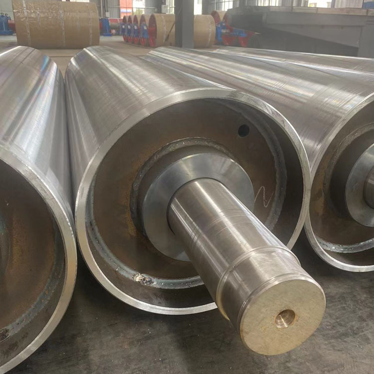
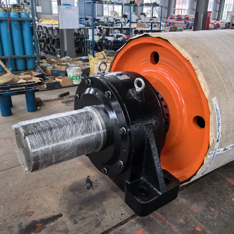
The J&M's Head Pulley, also called the driving roller or the driving roller, is an important part of the belt conveyor. It is usually located at the head of the conveyor, so it is also called the J&M's Head Pulley.
The main function of the J&M's Head Pulley is to connect with driving devices such as motors, reducers, couplings, etc., as the power source of the entire conveying system. When the motor starts, the J&M's Head Pulley will rotate following the rotation of the motor, and then drive the belt to perform circular motion, thereby realizing material transportation.
The surface of the J&M's Head Pulley usually has knurling or similar structures, which is to increase the friction between the roller and the belt and prevent the belt from slipping or deviating during operation. At the same time, the knurling design can also effectively disperse the pressure of the belt on the drum and extend the service life of the drum.
It should be noted that the selection and use of the J&M's Head Pulley need to be determined based on the specific conveyed materials, conveying volume, conveying distance and other factors. In addition, in order to ensure the normal operation of the conveyor, the J&M's Head Pulley needs to be maintained and inspected regularly, including cleaning the material residue on the surface of the roller and checking the wear of the roller.
After the drum is assembled, the radial runout tolerance of the outer circle shall comply with the requirements in the table below.
Unit:mm|
PulleyD |
200~800 |
1000~1600 |
1800 |
|
|
Radial circular runout tolerance |
Non-Lagging Pulley Pulley |
0.6 |
1.0 |
1.5 |
|
Lagging Pulley |
1.1 |
1.5 |
2.0 |
|
The pulley bearings are FAG or SKF bearings.
Main technical parameters of the drum-Radial runout of drum outer circle
Tail Bend Pulley
φ≤800mm≤1.05mm
φ>800mm≤1.40mm
Drive Pulley
φ≤800mm≤1.05mm
φ>800mm≤1.40mm
Static balance accuracy G40
Our quality assurance plan primarily defines the following points:
1.Inspection and control of equipment;
2.Control of purchased equipment or materials;
3.Control of materials;
4.Control of special processes;
5.On-site construction supervision;
6.Quality witness points and schedules.


Related Products
Tail Bend Pulley
Head Pulley
Ceramic Rubber Pulley